Transformer Formula Sheet
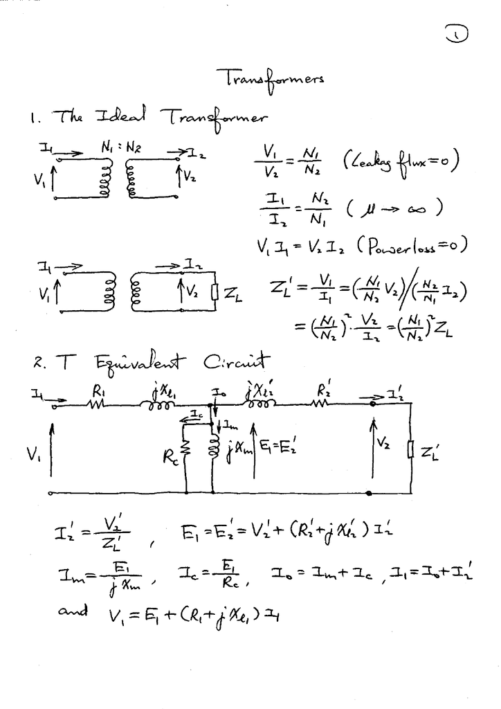
Transformer Formula Sheet - \[v_{s} = \frac{n_{s}}{n_{p}} \times v_{p}\] where, \[n_{p}\] = number of turns in the primary \[n_{s}\] = number of. Equivalent resistance of transformer windings: Emf induced in primary & secondary windings: Web as the transformer is basically a linear device, a ratio now exists between the number of turns of the primary coil divided by the number of turns of the secondary coil. Each inductor loop is in. Web figure 1 as seen in figure 1, the transformer has two inductors: A source (or primary) inductor (ls) and a load (or secondary) inductor (ll).
A source (or primary) inductor (ls) and a load (or secondary) inductor (ll). Equivalent resistance of transformer windings: Web as the transformer is basically a linear device, a ratio now exists between the number of turns of the primary coil divided by the number of turns of the secondary coil. Emf induced in primary & secondary windings: Web figure 1 as seen in figure 1, the transformer has two inductors: \[v_{s} = \frac{n_{s}}{n_{p}} \times v_{p}\] where, \[n_{p}\] = number of turns in the primary \[n_{s}\] = number of. Each inductor loop is in.
Each inductor loop is in. Web as the transformer is basically a linear device, a ratio now exists between the number of turns of the primary coil divided by the number of turns of the secondary coil. Emf induced in primary & secondary windings: Equivalent resistance of transformer windings: A source (or primary) inductor (ls) and a load (or secondary) inductor (ll). \[v_{s} = \frac{n_{s}}{n_{p}} \times v_{p}\] where, \[n_{p}\] = number of turns in the primary \[n_{s}\] = number of. Web figure 1 as seen in figure 1, the transformer has two inductors:
Transformer Formula Sheet
Web figure 1 as seen in figure 1, the transformer has two inductors: Web as the transformer is basically a linear device, a ratio now exists between the number of turns of the primary coil divided by the number of turns of the secondary coil. \[v_{s} = \frac{n_{s}}{n_{p}} \times v_{p}\] where, \[n_{p}\] = number of turns in the primary \[n_{s}\].

Current transformer (CT) saturation calculator EEP
Web as the transformer is basically a linear device, a ratio now exists between the number of turns of the primary coil divided by the number of turns of the secondary coil. Each inductor loop is in. A source (or primary) inductor (ls) and a load (or secondary) inductor (ll). Emf induced in primary & secondary windings: Equivalent resistance of.

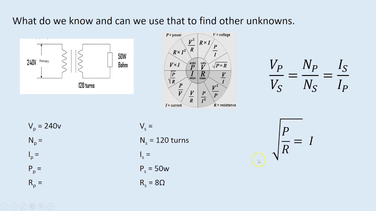
Transformer Calculation Sheet
Web figure 1 as seen in figure 1, the transformer has two inductors: \[v_{s} = \frac{n_{s}}{n_{p}} \times v_{p}\] where, \[n_{p}\] = number of turns in the primary \[n_{s}\] = number of. Emf induced in primary & secondary windings: Equivalent resistance of transformer windings: Each inductor loop is in.
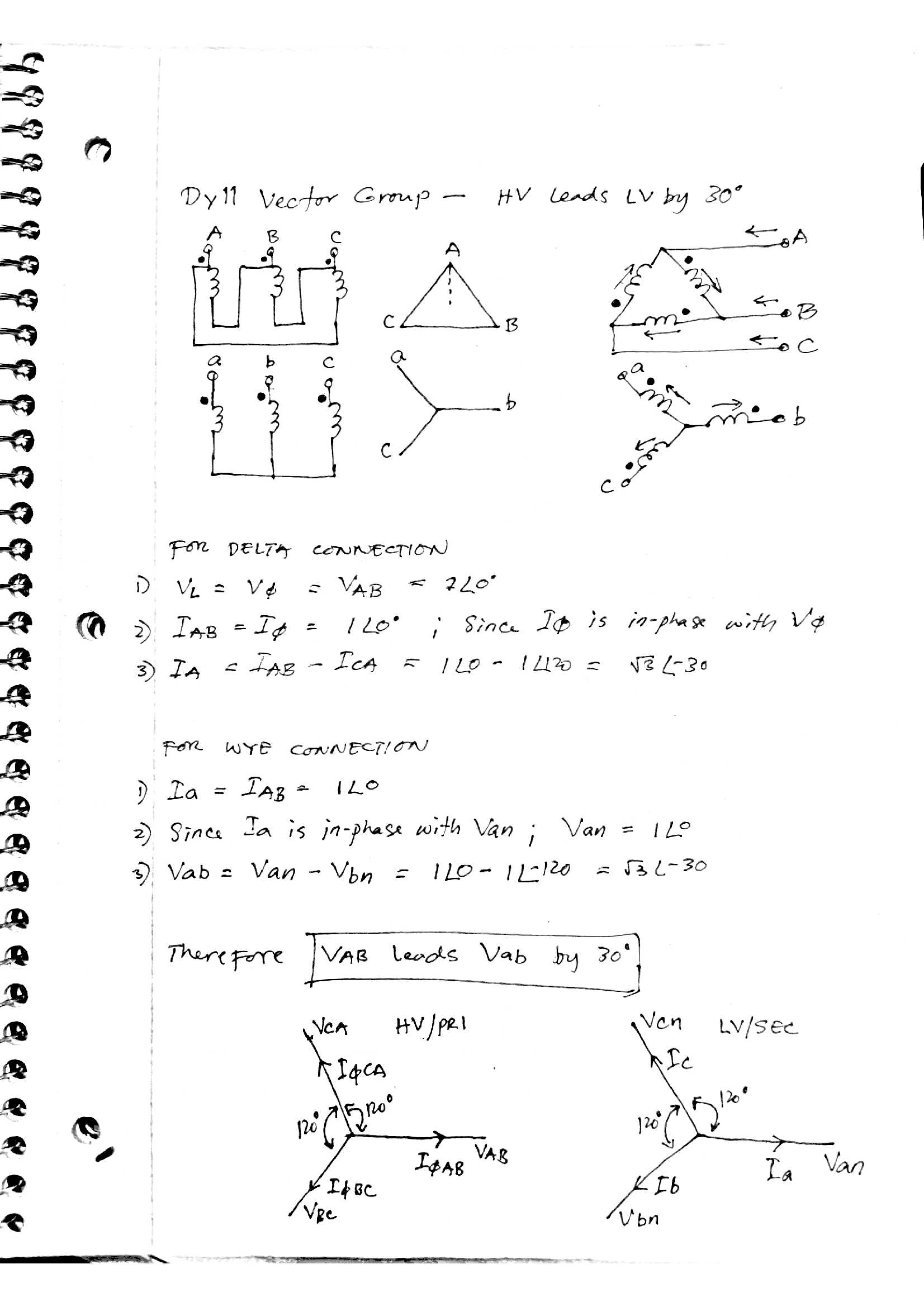
Transformer Vector Groups Basic Concepts Part 1 Electrical
\[v_{s} = \frac{n_{s}}{n_{p}} \times v_{p}\] where, \[n_{p}\] = number of turns in the primary \[n_{s}\] = number of. Emf induced in primary & secondary windings: Equivalent resistance of transformer windings: Web figure 1 as seen in figure 1, the transformer has two inductors: Web as the transformer is basically a linear device, a ratio now exists between the number of.

Simplifying the transformer equation YouTube
A source (or primary) inductor (ls) and a load (or secondary) inductor (ll). Web figure 1 as seen in figure 1, the transformer has two inductors: \[v_{s} = \frac{n_{s}}{n_{p}} \times v_{p}\] where, \[n_{p}\] = number of turns in the primary \[n_{s}\] = number of. Emf induced in primary & secondary windings: Each inductor loop is in.

Pin on Electrical
A source (or primary) inductor (ls) and a load (or secondary) inductor (ll). Web figure 1 as seen in figure 1, the transformer has two inductors: \[v_{s} = \frac{n_{s}}{n_{p}} \times v_{p}\] where, \[n_{p}\] = number of turns in the primary \[n_{s}\] = number of. Each inductor loop is in. Emf induced in primary & secondary windings:

Formula Sheet 2 Transformer Where N1 are the voltage and number of
Each inductor loop is in. \[v_{s} = \frac{n_{s}}{n_{p}} \times v_{p}\] where, \[n_{p}\] = number of turns in the primary \[n_{s}\] = number of. A source (or primary) inductor (ls) and a load (or secondary) inductor (ll). Web figure 1 as seen in figure 1, the transformer has two inductors: Web as the transformer is basically a linear device, a ratio.
Transformer Circuit and Equation YouTube
Web figure 1 as seen in figure 1, the transformer has two inductors: Equivalent resistance of transformer windings: Web as the transformer is basically a linear device, a ratio now exists between the number of turns of the primary coil divided by the number of turns of the secondary coil. \[v_{s} = \frac{n_{s}}{n_{p}} \times v_{p}\] where, \[n_{p}\] = number of.

Power And Distribution Transformers Sizing Calculations Part Eight
A source (or primary) inductor (ls) and a load (or secondary) inductor (ll). Web figure 1 as seen in figure 1, the transformer has two inductors: Equivalent resistance of transformer windings: \[v_{s} = \frac{n_{s}}{n_{p}} \times v_{p}\] where, \[n_{p}\] = number of turns in the primary \[n_{s}\] = number of. Web as the transformer is basically a linear device, a ratio.
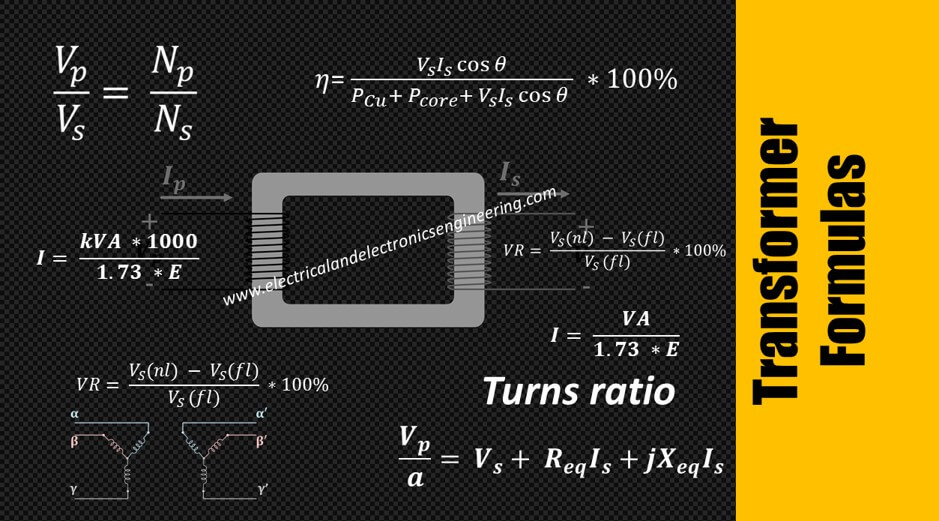
Top 10 Transformer Formulas Electrical and Electronics Engineering
\[v_{s} = \frac{n_{s}}{n_{p}} \times v_{p}\] where, \[n_{p}\] = number of turns in the primary \[n_{s}\] = number of. A source (or primary) inductor (ls) and a load (or secondary) inductor (ll). Web figure 1 as seen in figure 1, the transformer has two inductors: Emf induced in primary & secondary windings: Each inductor loop is in.
Web As The Transformer Is Basically A Linear Device, A Ratio Now Exists Between The Number Of Turns Of The Primary Coil Divided By The Number Of Turns Of The Secondary Coil.
\[v_{s} = \frac{n_{s}}{n_{p}} \times v_{p}\] where, \[n_{p}\] = number of turns in the primary \[n_{s}\] = number of. Equivalent resistance of transformer windings: Each inductor loop is in. Emf induced in primary & secondary windings:
Web Figure 1 As Seen In Figure 1, The Transformer Has Two Inductors:
A source (or primary) inductor (ls) and a load (or secondary) inductor (ll).